

Updated At: 2025-12-03
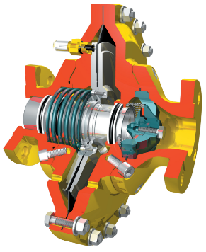
The CHTF series regulators are axial-flow, indirect-acting pressure regulators. Equipped with a pilot featuring a pressure-stabilizing structure and combined with the main valve’s axial-flow design, this series offers a higher flow coefficient and more stable performance, making it especially suitable for high/medium-pressure, high-flow regulator skids/stations.
Technical Specifications
| Maximum allowable inlet pressure | 100 bar |
| Inlet pressure range | 1–100 bar |
| Outlet pressure range | 0.5–80 bar |
| Pressure regulation accuracy class | AQ 2.5 |
| Lock-up pressure class | SG 5 |
| Operating temperature | −20 °C – 60 °C |
| Connection size (flange) | DN50 – DN150 |
Dimension Reference Table
| Model | Outlet | Outlet | L (mm) | H (mm) | H1 (mm) |
||
| (DN) | (DN) | DN40 | Class600 | DN40 | Class600 | ||
| CHTF50 | 50 | 50 | 254 | 286 | 144 | 682 | 165 |
| CHTF65 | 65 | 65 | 276 | 311 | 170 | 717 | 185 |
| CHTF80 | 80 | 80 | 298 | 337 | 195 | 744 | 200 |
| CHTF100 | 100 | 100 | 352 | 394 | 231 | 767 | 225 |
| CHTF150 | 150 | 150 | 451 | 508 | 330 | 936 | 295 |
Main Regulator Spring Reference Table
| Spring Color Code | Spring Parameters | FZL (Low-Pressure Type) | FZH (High-Pressure Type) | ||
| D | De | Lo | |||
| Yellow | 3.5 | 33 | 76 | 20–49 kPa | – |
| Yellow | 4.0 | 33 | 76 | 40–90 kPa | 80–180 kPa |
| Yellow | 4.5 | 33 | 76 | 90–150 kPa | 180–300 kPa |
| Yellow | 5 | 33 | 76 | 150–200 kPa | 300–400 kPa |
| Yellow | 5.5 | 33 | 76 | 200–275 kPa | 400–550 kPa |
| Yellow | 6 | 33 | 76 | 275–400 kPa | 550–800 kPa |
Flow Rate Reference Tables (Nm³/h)
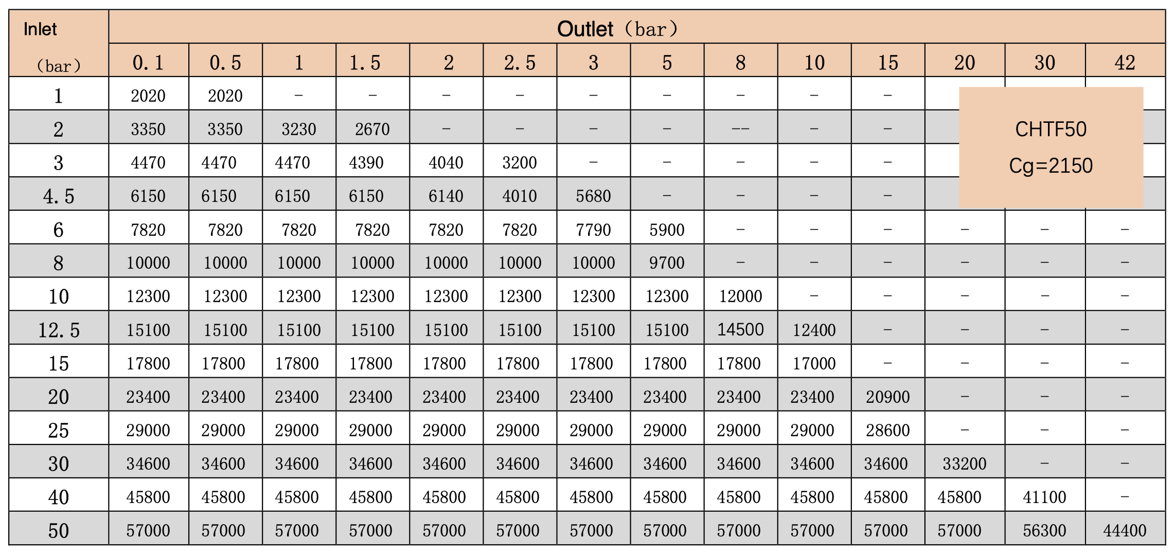

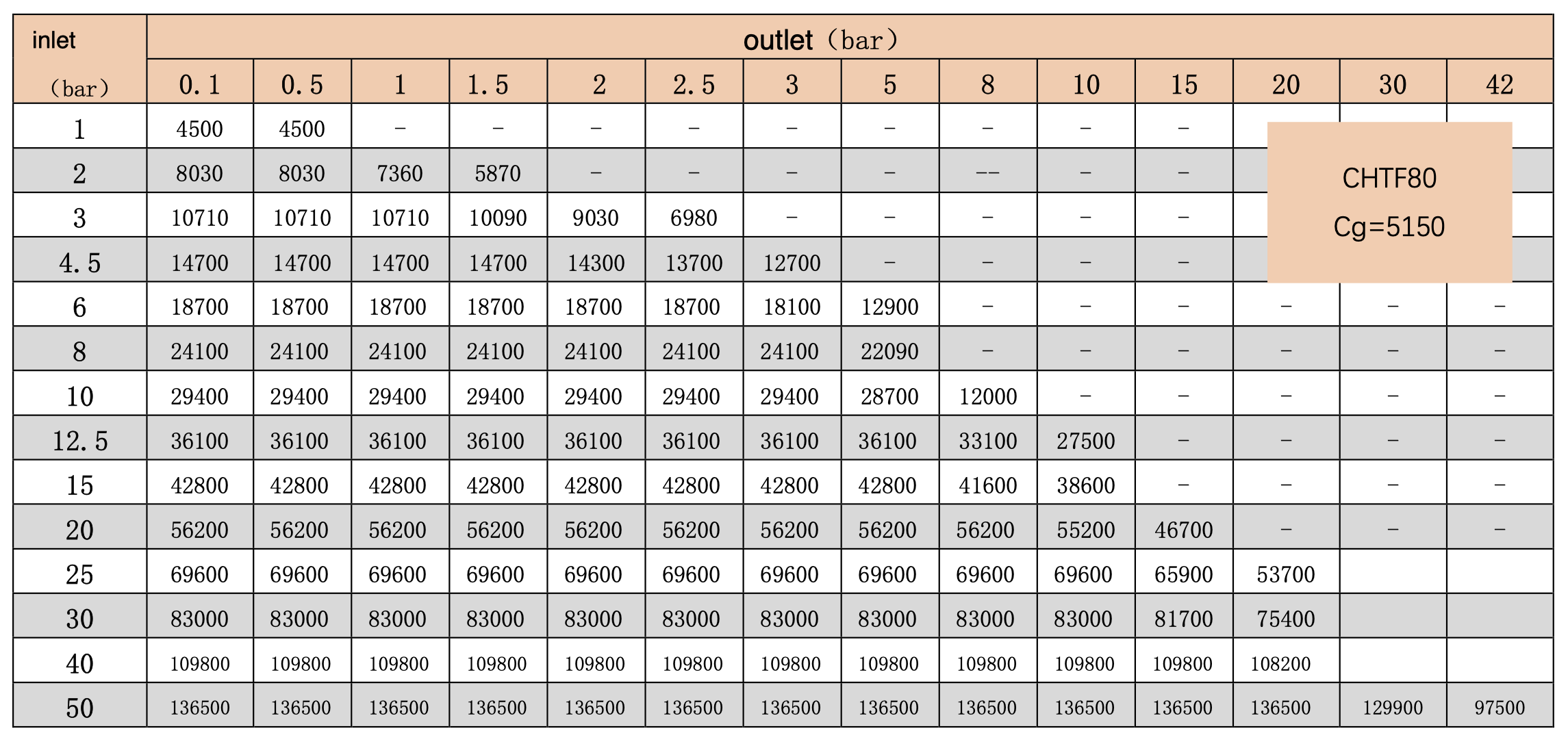
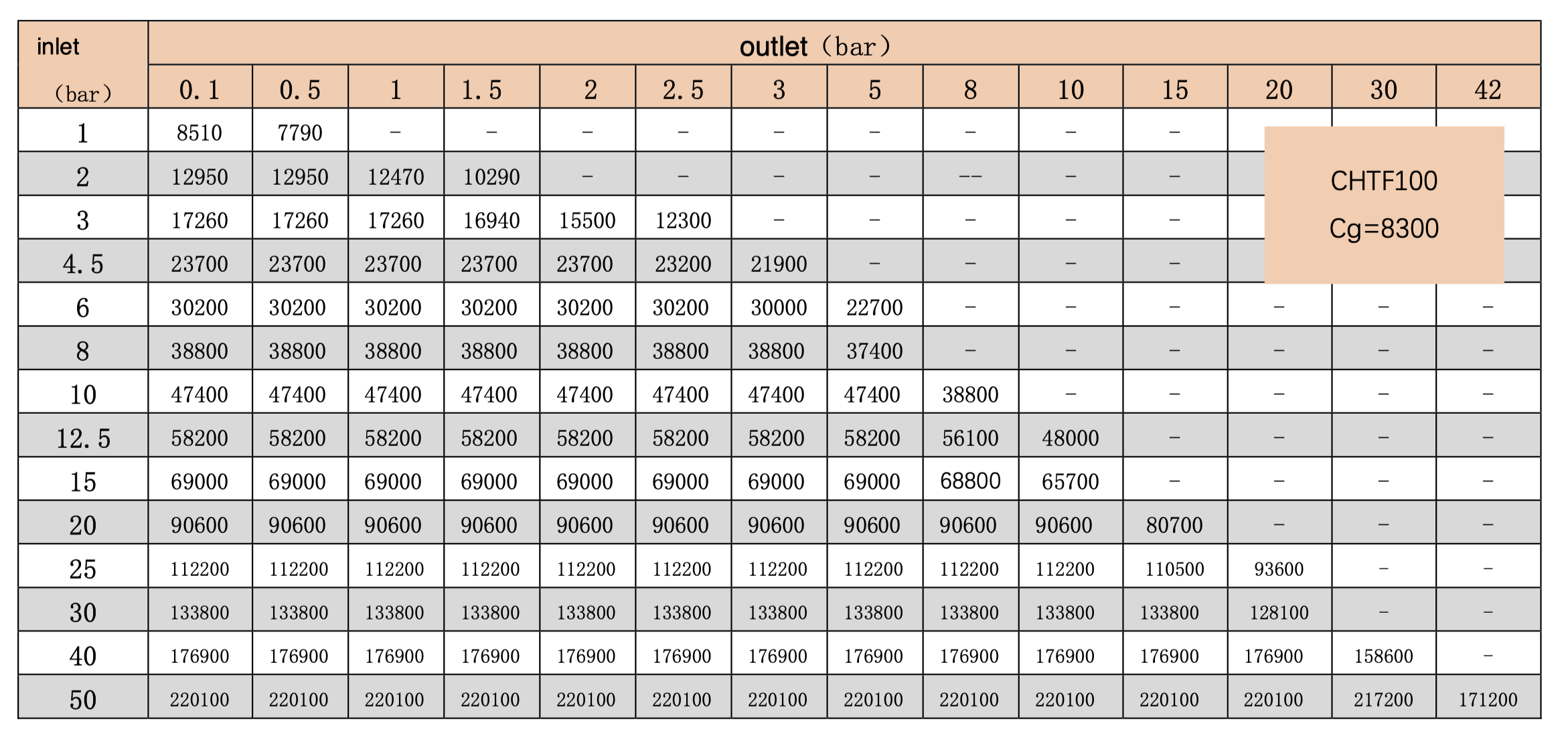
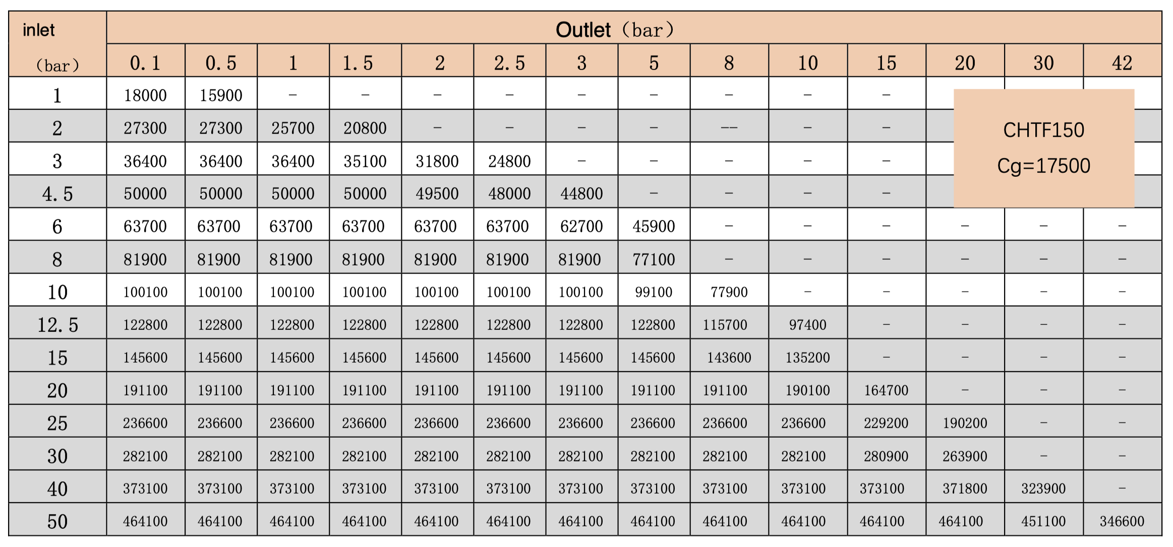
The flow rates shown in the above charts are based on natural gas with a relative density of 0.6 under standard conditions.